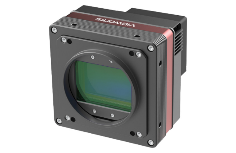
Vieworks Industrial Vision Color Cameras (i.e. VA-29MG2-C2 ) have image sensors with photosensititve sites called pixels. The pixels are exposed to light where light is converted into an electrical signal. The electrical signal is digitized and stored as an image captured. Silicon is responsive to light from the near UV (below 400 nm) to the near IR, or upto 1100 nm.

In order to capture color images from a single image sensor, each pixel must have a color filter. In early 1970s, a Kodak scientist, Dr. Bryce Bayer invented a method of creating color filters on pixels in a pattern. With the help of a mathimatical alogrithm, saturated color can be created from these pixels.
Each pixel is read and converted and stored. The stored image data represents only the color that is over the pixel but until the image is converted into color, it looks like a monochrome image except there are slight gray level differences from which is essentially a monochrome image. If the image before converting is viewed it will appear as if you were viewing the image through a window screen. With the Bayer CFA, a RGB three color plane can be derived. However, there are missing information on the primary colors in each plane which can be solved by using information from adjacicent pixels. There are many alogrithms but few are published. Public alogrithms are “nearest neighbor”, bi-linear, smooth hue, linear and a few adaptive forms.
BAYER COLOR FILTER ARRAY
Color Filter Array (CFA) on the sensor produces full-frame, accurate-color images. Kodak was granted a U.S. Patent for this CFA called a Bayer pattern. It is designed for progressive scan sensors. The array is composed of a kernel of 4 pixels. The filters are deposited during fabrication of the sensor. Two corner pixels are green while the opposite corners are blue and red. Three color values per pixel must be calculated, red-green (rmg), green (g), and blue-green (bmg). All of the green pixels, rmg and bmg must be calculated. At the red pixels, bmg must be calculated. At the blue pixels, rmg must be calculated. Color difference values are obtained from either horizontal, vertical or bilinear interpolation of the color difference values at the chroma pixels. Solving for the missing green pixel, g’ in the array is as follows:
Color Filter Array (CFA) on the sensor produces full-frame, accurate-color images. Kodak was granted a U.S. Patent for this CFA called a Bayer pattern. It is designed for progressive scan sensors. The array is composed of a kernel of 4 pixels. The filters are deposited during fabrication of the sensor. Two corner pixels are green while the opposite corners are blue and red. A custom IC was designed to calculate in real-time 24-bit color [RGB] by reading the Bayer pattern and interpolating the two missing color pixels. Three color values per pixel must be calculated, red-green (rmg), green (g), and blue-green (bmg). All of the green pixels, rmg and bmg must be calculated. At the red pixels, bmg must be calculated. At the blue pixels, rmg must be calculated. Color difference values are obtained from either horizontal, vertical or bilinear interpolation of the color difference values at the chroma pixels. Solving for the missing green pixel, g’ in the array is as follows:

line 1 B1 G1 B2 G2 B3 At a horizontal edge: missing green pixel (g’) = 1/2(G5+G6) [1]
line 2 G4 R1 G5 R2 G6 At a vertical edge: missing green pixel (g’) = 1/2(G2+G8) [2]
line 3 B4 G7 B5 G8 B6 Both edges or no edges: missing green pixel (g’) = 1/4(G5+G6+G2+G8) [3]
line 4 G10 R3 G11 R4 G12
line 5 B7 G12 B8 G13 B9
Using the missing green pixel (g’), the rmg and bmg values are calculated as follows for a red line:
line 1 B1-g’ G1 B2-g’ G2 B3-g’
line 2 G4 R1-g’ G5 R2-g’ G6
line 3 B4-g’ G7 B5-g’ G8 B6-g’
line 4 G10 R3-g’ G11 R4-g’ G12
line 5 B7-g’ G12 B8-g’ G13 B9-g’
examples:
horizontal interpolation rmg @ G5 green pixel = 1/2 [(R1-g’) + (R2-g’)] [4]
vertical interpolation bmg @ G5 green pixel = 1/2 [(B2-g’) + (B5-g’)] [5]
bilinear interpolation rmg @ B5 blue pixel = 1/4 [(R1-g’) + (R3-g’)+ (R2-g’) + (R4-g’)] [6]
bilinear interpolation bmg @ R2 red pixel = 1/4 [(B2-g’) + (B5-g’)+ (B3-g’) + (B6-g’)] [7]
Prior to these calculations, the pixels must have all offsets removed and be white balanced to achieve proper neutral tones. Other signal processing is done on the pixels after interpolation. Edges are enhanced to bring out fine detail by extracting the high frequency terms from the green field. These high frequency terms are scaled to ignore large edges. The pixels are next passed through a color correction & space conversion matrix for the RED, GREEN and BLUE color. These colors should correspond to the SMPTE XA/11 standard referenced in the CCIR, 709.
Bayer CFA spectral response will typically have double peaks for the red filter and sometimes the blue filter as shown below.

If these double peaks are not removed, the Bayer algrorithm will not produce saturated color. The Vieworks color cameras will have an IR cutoff filter to remove these double peaks above 720 nm. This filter will greatly improve the color rendering. We sometimes include a combination of UV & IR Cut filter for outdoor aerial applications.
Some additional references for CFA Demosaicking from Standford
